Sunday, February 8, 2009

February 8, 2009: Section 22 (continued!)


Page 22-02, step 13 called for riveting nutplates to the fwd side of the firewall bottom (F-1201C) at the "Return Line Clamp" location.

Step 14 was the tricky enlargement of the hole betw the gascolator attach holes (see Fig. 4). Directions call for drawing cross hairs to be sure that you center and keep centered while using the unibit to enlarge the hole to 9/16. I drew the cross hairs and then applied the unibit. I thought I was starting to drift so I stoped and drilled a pilot #40 hole, then tried the unibit again. This time I stayed on task and ended with a good result.

At this point, I went ahead and riveted the 8 holes (CS4-4) through the bulkhead into the engine mount brackets.

Page 22-03:
Step 1-2, Fabricating the "rudder pedal support channels" and dimpling holes and nutplate holes. This was a surprise to me because I would have thought that with material this thick, Van's would have you MCS. Dimple I did and it worked well.

Step 3, dimple then rivet nutplates to the F-1201B firewall shelf and F-1257 rudder pedal support channels. Be careful here. There are some switch-ups in both the type of nutplate and the rivets to attach them. I used AD3-3.5 six times when the plans call for AD3-4. Not a big difference, but I started the recovery process and drilled about half of them back out, replacing with correct rivet. I'll finish this redo tomorrow.

February 7, 2009: Section 22 (Continued)


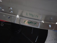
Page 22-02, step 10 was very easy and fairly quick. The hardest part about making the F-1201U spacers was finding the material! The directions note that you "curve parts slightly by hand in the following steps for a better fit." I did this, but didn't find it necessary to make much of a curve.

Step 11, was good and move fwd smoothly. Placing the spacer in the right place and carefully putting the F-12118 Cowl Attach Plates over it relies on this friction fit to hold it in place.

Step 12 depends on the friction fit while you match-drill #30 holes through the spacers and cowl attach plates, although one spacer was a wee bit out from where I wanted it. (I'm probably the only one that will ever notice this). In the photo you will notice that I wrote MCS on the cowl attach plate. I did this to ensure that I MCS on the proper side of the plate.

I was not moving at the speed of light and this all took me about 3 hours (bother terrapin).

February 4, 2009: Section 22 (Continued)

Page 22-02, step 7 was completed. Fabricated the F-1288 Cooler Stiffner by removing excess material from the angle bar and deburred.

Step 8, Riveted the cooler stiffner and nutplates to the firewall bottom.

Step 9 was a bit confusing because it is difficult to tell in figure 4 what the perspective is. I thought I was looking at the inside of the tunnel assembly. Checking the forum where Mich48041 (http://www.vansairforce.com/community/showthread.php?t=36239) identifies this "optical illusion" and points out that you are looking up from underneath, looking at the bottom. This helped! On to step 10 on Saturday.

February 1, 2009: Section 22 (continued)


Page 22-02, step 4. Final-drill #30 the WE-1204 Engine Mount Brackets to the tunnel ribs and then rivet these brackets to the rib. This went without incident.

Step 5, MCS #30 holes in fwd flange of F-1217A-L & R tunnel ribs. This too went smoothly.

Step 6, rivet the tunnel ribs to the fwd fuse skin and then cleco to this assembly the F-1201C firewall bottom & F-1271-L & R fwd fuse corner skin.

I don't show the corner skins attached, but I did add them after taking the pictures for that day. Van's has crammed alot of things onto this one page. I'll move to step 7 tomorrow (2/4/09).

Sunday, February 1, 2009

January 31, 2009: Infamous Section 22!


Pg. 22-02, Steps 1-3. Very confusing section! I was pre-warned, and I'm sure this helped but still challenging. (Note to self: make sure you check for updates each day that you work on plane. I thought I had the most current, but did not. Fortunately, I was not at the updated section yet which is on pg. 22-03.) On step 2, plans have you MCS nutplate attach holes on sloped flange of F-1217A-L & R (no problem), MCS all nutplate attach holes on F-1272 Fwd Fuse skin flush on the bottom side (I thought no problem), then MCS upper most hole in F-1288 cooler stiffener (again, no problem). There are holes on the F-1272 at the fwd edge, as well as further aft on the bottom skin. I've not done the holes aft. Step 3 has you dimple the nutplates, but this seems wrong because you've already MCS the holes. Also, this step calls for riveting the nutplates to the F-1217A-L & R, as per the callouts in Feg. 1. This callout cannot be seen, or maybe I'm blind! I'll give this section more thought and go to the forum (again) to see if I can figure it out.

January 25, 2009: Step floors, attaching F-1207B bulkhead...


Pg. 21-19, Installing the step floors into place. The most challenging part of this page was reaching through the lightening holes (step 4) to rivet the nutplates into place. After a few trials on each nutplate, I would get lucky and hit the mark. They say even blind squirrels find nuts sometimes! Installation of the floors, the F-1048 facet pump bracket all went without incident. I'm getting good at nutplate fabrication/installation.

Moved to pg 21-20 (last page of this section) to install 6 "systems block studs." Wendy helped me with this because it is impossible for one person to turn the screw and hold the nut. To prep for this, I put oil on each stud and screwed the nut on each, up to the stud head, then took it off. I'm glad I did this because without the oil I think I would have ruined the stud head (philips). As it was, this went very well. I used the electric drill to screw the bolt into the nut, which Wendy held in place using vice grips.

January 24, 2009: Riveting step attach angles, nutplates, etc.

Pg. 21-18, Riveting the Step Attach Angles, corner skins and installation of nuteplates/snap bushings. All went well with riveting bulkhead attach angles, etc. I'm still a bit uncomfortable with using the correct torque on the bolts but will continue my study of this and asking for advice along the way. Using the table provided by Van's and torqued the step bolts to 60 inch pounds.

Installation of the bushings came next, followed by work on the step floors (pg. 21-19, steps 1-2).

January 23, 2009: Step Attach Angles

Pg. 21-17, step 7-9 went well. I am taking a lot of time, but finding that since this is not a race, I'm better off this way. On step 8, the directions call for you to make the step pad horizontal, however, make sure the "the inbd. Top corner of the step is to remain even with or below the beginning of the radius of the F-1202F bulkhead." What's the radius of the bulkhead? I was scratching my head on this one, but the drawings are clear and having Wendy read the directions too, it became clear. So, the pad looked horizontal and the top corner was just below the curve of the flange on the top of bulkhead, and I did my drilliing and things worked out well. After all holes were drilled, I took things apart and primed the F-1236A-L & B-L.

January 23, 2009: Step Attach Angles & Match-Drilling


Pg. 21-17, step 7-9 went well. I am taking a lot of time, but finding that since this is not a race, I'm better off this way. On step 8, the directions call for you to make the step pad horizontal, however, make sure the "the inbd. Top corner of the step is to remain even with or below the beginning of the radius of the F-1202F bulkhead." What's the radius of the bulkhead? I was scratching my head on this one, but the drawings are clear and having Wendy read the directions too, it became clear. So, the pad looked horizontal and the top corner was just below the curve of the flange on the top of bulkhead, and I did my drilliing and things worked out well. After all holes were drilled, I took things apart and primed the F-1236A-L & B-L.

January 23, 2009: Step Attach Angles

Pg. 21-17, step 7-9 went well. I am taking a lot of time, but finding that since this is not a race, I'm better off this way. On step 8, the directions call for you to make the step pad horizontal, however, make sure the "the inbd. Top corner of the step is to remain even with or below the beginning of the radius of the F-1202F bulkhead." What's the radius of the bulkhead? I was scratching my head on this one, but the drawings are clear and having Wendy read the directions too, it became clear. So, the pad looked horizontal and the top corner was just below the curve of the flange on the top of bulkhead, and I did my drilliing and things worked out well. After all holes were drilled, I took things apart and primed the F-1236A-L & B-L.

January 17, 2009: Step Attach Angles and Nutplate Bracket

On this Saturday, I spent 4.5 hours on the plane, pg. 21-16 & 17, riveting the bottom skin and stiffeners into place. No problems here, just keep at it!

Then, moved onto step 1 on page 21-17 and this went well for a time. I read the directions carefully but not carefully enough. The plans call for you to separate the F-1236 Step Attach Angles and then step 2 calls for trimming "2" of the attach angles. Things were going so well and I was so engrossed in doing a good job with trimming, deburring, etc. that I did all 4 attach angles. FRUSTRATINGLY dumb mistake. (Monday, I went to Van's and bought more angle. Once I recovered my calm, I went on to make the nutplate brackets and MCS as called out.

January 15, 2009: Bottom Stiffeners & Nutplates & Bottom Skin...


Separated F-1204Z bottom stiffeners and F-1268A-E Doublers without incident. Be sure to mark the doublers to facilitate their correct placement. I used the nibbler that Jim Cone mentioned and it works very well to separate parts.

After this fabrication work, moved on to page 21-16 and completed the dimpling and attachment of nutplates around access holes. Step 3 on that page calls for breaking the edges along both sides for the F-1276 bottom skin. For this, I used the tool pictured, available from Avery.

January 15, 2009: Bottom Stiffeners & Nutplates & Bottom Skin...

Separated F-1204Z bottom stiffeners and F-1268A-E Doublers without incident. Be sure to mark the doublers to facilitate their correct placement. I used the nibbler that Jim Cone mentioned and it works very well to separate parts.

After this fabrication work, moved on to page 21-16 and completed the dimpling and attachment of nutplates around access holes. Step 3 on that page calls for breaking the edges along both sides for the F-1276 bottom skin. For this, I used the tool pictured, available from Avery.