Wednesday, January 14, 2009

January 12-14, 2009: Fuselage Corner Skins


pg. 21-15 Attaching the corner skins presented no challenge. I dd tape the holes that were not to be riveted. Then moved onto the F-1274-R & L fuselage corner skins, again without problems.

Sunday, January 11, 2009

January 11, 2009: Control Column, Step Ribs & Snap Busings


Today was spent on pg. 21-14. I installed the control column using tweezers! That's right, tweezers. It's a tight fit getting into the area to slide the bolt through, along with the appropriate washers. Following the directions which suggested using tape to hold the washers, I improvised a bit and taped the washers together (2 side by side, two sets per bolt) and used tweezers to position the washers while sliding the bolt into place. Worked Great!

Then moved onto step 2, more dimpling and deburring, to install the step ribs (pg. 21-14). All went well and the ribs are installed. Next, prepared the F-1202F bulkhead, clecoed into place (DO NOT RIVET).

Now, here is where it got interesting. The next step, step 7, calls for installing snap businging on bulkheads. One problemo, Bulkhead F-1204A is missing one hole and another is undersized. On the forum, JTE identified this back in December, but I did not remember it for when I got to this stage. I'm going to write to Van's and get a reply, in writing, so that I can include the reply in my builder's log. Then, onto the curve skins!

January 10, 2009: F-1203A Bulkhead (cont.)


Staying on pg. 21-11 I started this Saturday's building extravanza on step 3. I spent about 4 hours on steps 3-5. It was at least twice as long as necessary because I didn't pay enough attention to which side of the bulkhead to install the Control Column Mount Assemblies and started right off putting the first one on the wrong side. If that wasn't enough, I had used the wedge tool to put the rivets in, and the shanks broke off a good 1/4 inch above the rivet. Correcting this mistake was problematic. To make things even worse, I also had installed the nutplates which were even more challenging to remove. PAY ATTENTION!!! This misstep cost me time and degraded the quality of the build a bit.

Moving on to pg. 21-12 was good. No significant challenges, but again, pay attention to what the plans call out in terms of where to dimple. I took the advice of others and taped off those nutplate holes that were NOT to be dimpled. The challenge on this page is how to position the bulkhead so that you can use the hand squeezer to make the dimples.

Pg. 21-13 is prett straight forward, but I was careful and took plenty of time to read & re-read the riveting instructions. Be sure not to rivet the F-1253 L & R. You will need to work the control column through this location and will need to bend this part of the way to make the fit. On step 5 the plans indicate to final drill the 3/8 inch hole to 1/2 inch. I did this on the drill-press using the uni-bit and it went well. Be sure to do the FORWARD hole as identified.

One question came up in my mind when I got to riveting the seat ramp floors to the F-1215 seat ribs. Some of the ribs that had dimpled holes on the upper flange did not need the dimple as the plans call out using a LP4-3 rivet. Oh well, I hope this is correct.

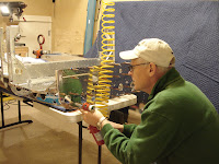
Finished the night by inserting the control column through the lightening holes. This took a bit of maneuvering, but with gentle persistence it went into place. Tomorrow I'll pick up on pg. 21-14.

January 9, 2009: F-1203A Bulkhead (cont.)


Pg. 21-10: F-1203A Bulkhead
I picked up from the last session on step 6 with the final drilling of 4 bulkhead holes as called out in "detail A." Using the uni-bit on the drill press worked great here and resulted in round correctly spaced holes. The tricky part was step 7. The hole that had "hatched area" to be removed with "dike/wire cutters", neither of which I had. So, I used snips to carefully make cuts in the hatched areas and was able to snip away a little at a time. The I used a file to finish. Wanting to be sure I had the hole correct, I read ahead in the plans to locate what was intended to go through the hole so I could use it to check size of hole. Unfortunately, I could not find a future reference to this hole (must be in the finishing kit section). Machine counter sinking of holes went fwd smoothly.

I primed the non-alcad F-1203C stub spar receptacle with the self-etching rattle can primer from NAPA.

Step 10 has you final drill #30 any holes in the process of putting the stub spar receptacle assembly together if the holes are too tight. I found that if I clecoed the parts together and then insterted a hole punch in the hole (like Jim Cones use of an awl) to sort of "wiggle" around, helped line up all the holes. No final drilling was necessary to make the parts fit.

I then moved to step 1 on p. 21-11, separating the 2 F-1203E Bulkhead Doublers and deburred. Before quiting for the night I installed these on the bulkhead, being sure to put them on the appropriate side of the bulkhead (very important!).

January 7, 2009: Stub Spar Assembly and F-1203A Bulkhead


Worked on F-1203A bulkhead and final drilling holes to 7/16 & 3/4. This went very well using the "step" drill and the drillpress to do the job. Holes turned out uniform and appropriately placed. Next I removed metal on the final large hole (see p. 21-10, step 7). I used the tin snips to remove some of the material and filed the rest. The result is good, but cannot be certain it is perfectly circular, but it looks like it. I read ahead in the plans to see what will go through this hole so that I could test it, but could not find anything. This may be something in the finishing kit. I also prepared the F-1203C Stub Spar Receptacles, deburring and filing to create a close fit to the rounded ends of the stub spar assemblies. Then primed this part.

Tuesday, January 6, 2009

January 6, 2009: Bulkhead Caps, Rollers and Control Column


I started the evening build on page 21-09 and completed steps 2-5 in about an hour. As usual, the deburring took about 1/3 of this time. Riveting the bulkhead caps in place was straight forward. I took the advice of others and taped over the holes that were NOT to receive a rivet. I think this is a good strategy compared to using a marker.

Installation of the rollers (step 5) was also easy. The only question I have is how much to torque the bolt. I took care here so as not to strip the nut plate as well as making sure that the roller still rolled. (I don't know, but I think the nutplate has a natural tendency to act as a locknut.)

Then after dinner, I completed steps 1- 3 on page 21-10. At least 20 minutes of the time was spent scratching my head to figure out what was called for in terms of MCS the rivet holes. (I'm learning a lot here but loosing hair!) Deburring was thorough to be sure the parts matched and fit well. My biggest challenge was counter sinking the rivet holes. Before MCS the actual part, I test the depth on scrap material. Still, sometimes the countersink is too deep, while other times it is perfect with no change in the cage.

Monday, January 5, 2009

January 5, 2009: Completion of the Seat Floor Assemblies


I spent about 2.5 hours tonight on the seat floor assemblies and all went well. The close-in hand rivet squeezer is a must for riveting the seat ribs to the bulk head. I also used the wedge tool I fabricated following other's example, e.g. Jim Cone, Rudy, etc.

Tomorrow I will move on to working the right bulkhead cap and roller on page 21-09.

January 3-4, 2009: Mid Fuse Ribs & Bottom Skins


The photos on this entry may be in reverse order. I prepared all the seat rib assemblies, involving dimpling, installing platenuts, etc. All went well till I got to page 21-05, step 12, and began installing the flaperon mixer bracket. It was here that I discovered that I had put the mixer together incorrectly. Fortunately I discovered this before riveting or doing any damage. The image on the left shows the incorrect assembly.

I didn't trust that I had installed the rear spar recepticle correctly so the photo shows that I tested the fit by taking the assembly to the wing and testing the fit. It fit very well so I am happy.

All went well after this. It was tricky on page 21-06, step 7 with cutting the seatback hinge. Thankfully I had kept up Van's forum and found a caution there to measure an extra .5 inch so that I made the cut at 10.5 inches instead of 10. This allows for the hinge to be identical to the one depicted on this page. My screw-up here was in removing the center 2 eyelets on each hinge. I tried to cut these with a hacksaw, but there was not enough space for the blade. I then went to the bandsaw, but because my blade is too coarse, I strayed off and made a mistake with the cut. I ended up using my scotchbrite wheel and this worked the best.

We had snow over Christmas and all our fantastic adult children were home for the Holidays (sounds like a song coming on!). The snowy house picture is our Christmas card and also helps explain why I was away from the RV-12 for the better part of 2 weeks.

The plans are very clear and with thorough reading (and re-reading) one should not have a problem here.